Ground Control – Final Project

This project came at a rough time for me.  My capstone project and internship were both coming to a head at the same time as this, so I wanted to do what I could to make my final project here something I could enjoy working on – easing the burden.  The project’s prompt was to make something using any two of the previously used prototyping methods, plus a video.  I was hoping to make something using the laser cutter and 3D printer, but was stressed to the point that I couldn’t come up with anything interesting to do with them.

Enter Derek, the Project Manager of my capstone project.  He expressed some dismay that he had the basic idea of a project for the laser cutter and 3D printer, but nobody to work with to flesh it out or divide up tasks.  I was already on board to partner up before he told me his ‘I-can’t-believe-I-didn’t-think-of-that’ idea of making a board game.

Research

Neither of us had created a board game previously, so we started by searching the internet for inspiration.  There are many excellent board games out there, as well as sites and communities devoted to people airing ideas for new ones.

We came across an idea for a cooperative airport-themed game on a site called Board Game Designers Forum.  The idea was for a two-player game where the players tried to get the airplanes sequenced and ready to take-off from an airport.  We liked the idea of a hex-tiled two-player airport runway game, but we wanted to use this as the basis for a game of our own design.

Design
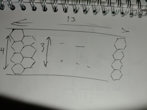
13 x 4 design sketch

We started by generating sketches of what we wanted the game to look like. Using the premise of a runway-themed two-player game, we created the hexes.

We began by creating the general shape of the runway with hexes.  Since it needed to be longer than wide, we quickly sketched out a board 13 hexes long and 4 hexes wide.  We decided that instead of a cooperative game, this would be a two-player head-to-head game, with one player taking one end of the runway and another with the other.

The most imperative maxim that we held when we designed Ground Control (as is the case when designing games in general) is to preserve balance.  Players cannot have such a one-sided game that victory is unattainable or unexciting.  Furthermore, the game must be quick-paced enough to not become boring, but long enough as to encourage strategy.
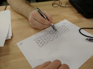
 

Board design and movement discussion: paper bits represent planes and trucks

Our two favorite board games are Ticket to Ride and Settlers of Catan, and we were heavily-influenced by their dimensions of strategic resources, building the edges of the hexes (Catan), and ticketed point-to-point connections (Ticket to Ride) among other aspects.
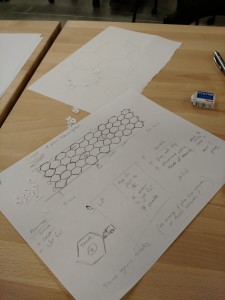
 

Design sketches for Ground Control

In Ticket to Ride, players try to accrue the most points by connecting cities with railroads.  They collect points by the rail laid, but also by connecting specific cities together.  These objectives are given by random cards, or tickets.  We designed Ground Control’s tickets to behave similarly, in that the number points are equal to sum of the required resources.

Settlers of Catan scores by having the most settlements, longest road connections, and other point-scoring schemes.  In Catan, players connect to resources by having settlements on the vertices of resource hexes, and these are connected to other settlements by hex-edge-long road segments.  Unlike Catan, we felt that having every hex be a resource would be overloaded in Ground Control.  We simplified the resource collection by only requiring a truck connection to the end of the runway, eliminating settlements, and having only certain hexes be resource spaces.

Ground Control Rules
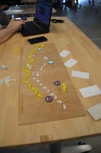
A game of Ground Control with well-completed supply lines

Ground Control is the name of my final project for this course.  It is a strategic two-player board game where players try to be the first to 25 points by completing randomly-assigned tickets.  Individual tickets have point values between 7 and 14 points.

In order to complete a ticket, players must move one of their two airplane tokens from hex to hex to the other side of the board, where the plane ‘takes off’.  However, tickets require specific resources to complete: fuel, water, and snacks.  Each resource must be collected by players from one of the six specific resource spaces. Players can collect from a resource spring only if they have a line of supply trucks (total of 24 per player) running along the edges of the hexes connecting from the spring to their end of the runway.

Each turn, two six-faced dice are rolled. The player may either:

  • Move trucks along the edges of the hexes equal to the sum of the numbers on the dice
  • Collect one resource from a connected resource space
  • Move planes equal to half of the sum of the numbers on the dice, rounded down
  • Draw three tickets cards and keep at least one

At the beginning of the game players randomly draw three tickets and must keep at least one, though they can elect to keep two or all three.  Resource spaces are located evenly on the board, but the space’s specific resources are randomly assigned at the beginning of the game.

Ground Control forces players to exercise strategy. Users may move planes too vigorously to find that they don’t have the resources to complete the tickets.  Too ambitious tickets may be drawn and player neglect their resources or plane movements.  Conversely, too many conservative, low-point value tickets may require more plane movements.
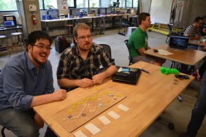
Derek and I showing off Ground Control at the Prototyping Open House (photo credit: Lukas Eiermann)

Laser-Cut Game Board


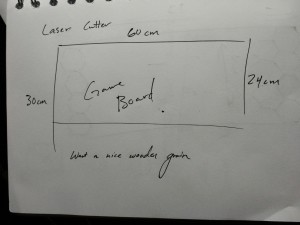
Board dimension sketch

Once we had the game rules and design figured out, we began our designs on the game board.  We measured the laser cutter and found that the maximum dimensions were 60 x 30 cm.  We wanted a long board, so we maximized the length at 60 cm.  For the width, we decided that it would be variable between 20 and 30 cm (and aimed for 24 cm).  I created the board’s design in Rhino and Derek bought the pressboard to be cut as the game board.

Designing the board was a simple matter for the most part.  I created a 24 x 60 cm rectangle and a hexagon within it, which I copied to make a column, then copied the column to make the rest of the board.  The most difficult part of the process was positioning, as I had a tendency to miss clicking the selected objects by a few pixels, deselecting the entire group.  I scaled it up using the Scale2D command (which I had not used before), leaving some padding inside the rectangle for aesthetic effect, but also to add the game’s title and our names to the board.

I also added scored circles to the resource spaces to signify them, which proved more difficult than I anticipated.  Because I did this after scaling the board, the hexagons were no longer centered on integers of millimeters and I had to hunt through the various object-snap options to find a way to locate the center of the hexagon.  After a lot of headaches, I ended up doing this by finding the intersection of two lines travelling through the midpoints of the hexagon’s sides, ending up with a board ready to print.
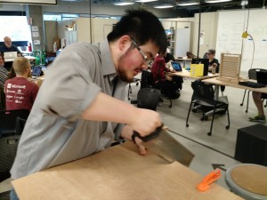
 

Derek cutting the board with a handsaw

Unfortunately, the store Derek bought the board from didn’t have a working saw to cut the 60x120cm board, and there were no power saws in our class workspace.  Instead, we clamped the board to the table and roughly sawed off the end of the board at the 30 cm mark with a handsaw.  The Rhino design came out to be 60 x 24 cm, allowing us to center the design on the 60 x 30 cm board, discarding the rough cut edge.

3D-Printed Trucks and Planes

The tokens for Ground Control were printed with the Makerbots that we used in the 3D Object Prototype assignment.  We needed to design the trucks and planes to fit the game board with its 3 cm long hex edges.

Planes
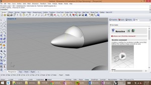
 

Screenshot of Rhino
Screenshot of Rhino

We started by designing the planes.  Initially, Derek wanted realistic-looking planes, beginning by designing a model of a jumbo jet in Rhino.  However, this proved to be very difficult, so he began looking for models already created on Makerbot Thingiverse.  One that he found looked exactly like what he wanted to build, so he downloaded it and scaled it to fit between 3 and 3.7 cm to fit in the hexes.
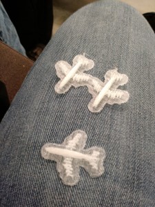
 

First draft of the 3D-printed planes

The quick print did not turn out well.  The wings were so fragile that they broke off when we tried to free them from the raft, and one even broke just by touching it.
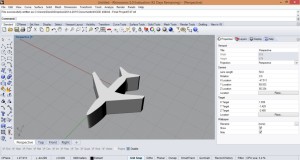
 

Rhino screenshot of the silhouette design

He went back to the drawing board and completely revamped the design.  Like icons and signs depicting planes, he shifted to a silhouette design for the plane tokens.  This design was the outline of a Boeing 747, traced, and raised to 1 cm high.  With fewer parts sticking out, these tokens printed out nicely. They are immediately recognizable as planes, and are sturdy enough to hold up during gameplay.

As an added bonus, the planes could be stood up in multiple ways — laying flat, on their tail fins, and between the wingtip and either the nose or tail fin.  We thought it might be an interesting way to indicate some sort of status during gameplay, but didn’t end up adding anything to Ground Control at that point.
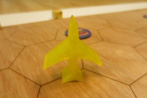
 

Completed plane token

Trucks

The small trucks were simple to design and execute, but unlike the plane, the printing itself was problematic.
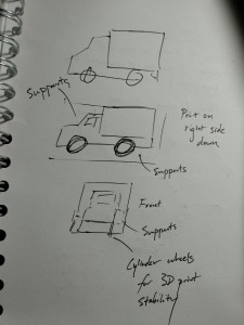
 

Truck sketches
Truck sketches

We had the design for the trucks early on.  They were 2 x 1 cm long and shaped like a delivery truck.  The cab was 1 mm narrower than the container end on each side, to make the truck shape immediately recognizable.

To print, we wanted to minimize the amount of supports and rafting needed.  However, the cylindrical wheels meant that it wouldn’t be smart to print with the wheels down. Instead, as to maximize surface area, we printed the trucks flipped onto their right side, requiring a few supports (for the 1 mm narrowing).

Our first batch of 24 trucks was printed with both the raft and the supports.  The raft made the print clean, but proved to be difficult to remove in about 2/3 of them — 1/3 of the trucks removed cleanly, while 1/3 had bits that we were able to remove and 1/3 had the raft stubbornly stuck.  On those where the raft simply could not be removed, we could only sand them down a bit, leaving unsightly bulges on the right side.
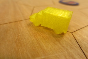
 

Completed truck
Completed truck

Not looking to repeat this, we decided to print our second batch without rafts, but with supports.  This eliminated the problem of the raft, but introduced a new one: stringy supports.  Without the raft, the supports weren’t built correctly, and without the correct supports the right side of the truck cab did not have a clean edge.  This required light sanding, but still did not look as good as the first batch.  Despite this, we agreed that this was still an improvement over wasting time with the stubborn rafts.

Printing woes

In addition to the issues that we faced with the 3D print designs, we had issues with the printer itself.  We chose yellow for our first set out of convenience — the only Makerbot available was already set up with the yellow PLA material.
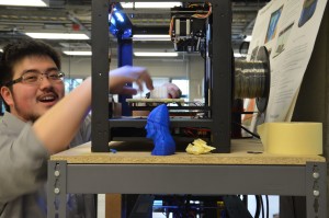
 

Derek prying prints off the printer platform (photo credit: Lukas Eiermann)

For the second set, we needed a different color.  We decided to go with red; however, the spool of red material had a tangle in it, and about halfway through our print the nozzle stopped feeding material, which we only realized when the print had ‘finished’ our two-hour print with our models left open.  With the Makerspace closing for the evening, we set up another print to run overnight, only for that to tangle as well.  Calling the spool of red PLA a lost cause, an attendant arriving in the morning reprinted our models on a clear white PLA, which finally resulted in a successful job.

Tickets and Resources

The next step was to create the destination tickets and resource tiles.

Destination Tickets

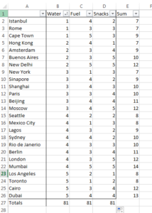
To make the game balanced, we needed tickets that didn’t favor one resource over another.  We agreed to have 25 tickets whose point values differed, but when added together, the number of resources would balance out.
 

Destination Tickets
Excel sheet with ticket destination totals

To that end, Derek created a list of 25 destinations and compiled them into Excel.  Each destination had three columns for the resources water, fuel, and snacks, and a total of these three.  Each column had a total at the bottom.

Once he ran a heuristic to see that there was a good spread of points per ticket, Derek went through to make sure that there were no requirement duplicates (e.g. both Cape Town and Hong Kong requiring 3 water, 4 fuel, and 3 snacks).
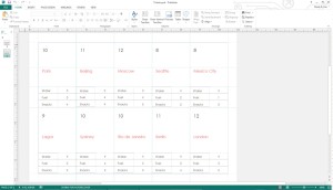
 

Card designs in Microsoft Publisher

The tickets themselves were created in Microsoft Publisher, using a vertical business card template.  Included on each ticket is the point total, the name of the city, and the water, fuel, and snack requirements.
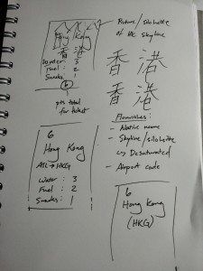
 

Ideation sketches for a Hong Kong destination card

Future work would have us add more design flair to the ticket destinations.  Initial sketches had us give interesting designs to the cards, such as the name of the city in the local language, the airport ICAO code, and a picture of the skyline or something that they city’s known for in the background.  Unfortunately, time constraints forced us to only provide the simple design.
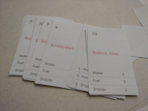
 

Completed tickets
Completed tickets

Resource Tiles

The next items to design were the resource tiles. The resource tiles would be both at the spaces and be collectible for use when taking-off and completing a ticket.
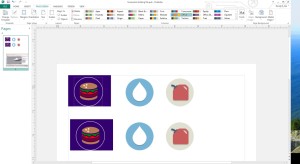
 

Modified icons on Microsoft Publisher

I printed off a few 3 cm diameter circles on some chipboard in the laser cutter and Derek found some free-use icons online, modifying them slightly.
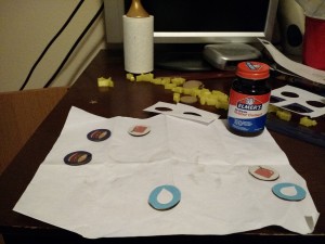
 

Icons affixed to the chipboard rounds with rubber cement

Derek printed these icons, then affixed them to the chipboard rounds with rubber cement.
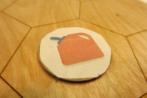
 

Completed fuel resource tile

Iteration and Video

Our next step was to actually perform a user test.  For us, this was quite easy — we just got two people to play our game.  We were relieved to find out that our concept was good — the game was fun and enjoyable.  We did record a few tweaks that affected the gameplay:

  • Movement of planes equal to half of the sum of the numbers on the dice, rounded down (was originally just one hex)
  • Needed more resource tiles
  • Set goal to 25 points (was originally undetermined)
  • Rebalance the tickets (have more variation in points per card, more unbalanced resources per ticket — some should require 0 of a resource)

Video

To create a video demo of Ground Control, we filmed together using equipment that we had for our capstone video and also took some promotional pictures of the game board.  We did primary shots of different game actions, such as redeeming a completed ticket once a plane takes off, moving trucks for the supply line, and gathering resources.

Unfortunately, time constraints meant that the filming was all done the afternoon before the video was due.  While Derek wrote up a final report on the project, I wrote the script, provided the narration, and did all the film editing on iMovie, bringing the 10 minutes of footage to fit into a 60 second time limit. Unfortunately, the pop filter I used with my microphone for voice acting was broken, making some of the harder consonants of his narration sound rough.  My voice had also become raspy by the time I had the opportunity to record the lines, making my vocal control tenuous at best.  At 5:30 AM I had finished editing the demo, just in time to get ready for the school day.

Lessons Learned
 

Derek (L) and myself (R)

Derek and I had a fun time working together and on Ground Control.  Although designing a board game, dealing with weird 3D prints, and having to use handsaws to cut boards is not easy, we had a good time doing so.  It provided a nice relief from our capstone project for us.
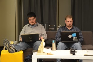
 

Us working (photo credit: Andy Davidson)

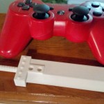
One major thing that we learned was that 3D printing is still new and developing.  While my Buster Sword printed out nicely and removed from its raft with ease, with Ground Control, we learned that size matters.  3D printers choke on small objects like our planes and trucks.

While it wasn’t quite a lesson learned, trying to edit a video overnight resulted in a lesson reinforced.  It is no small or easy task to make even just a one minute video, especially without all of the tools prepared beforehand.  Looking back, I’m not sure if it would have been possible to schedule this any better than we did, but that doesn’t stop it from serving as a reminder for any video work done in the future.

Thank you for reading!
Mobile Prototype

The next prototype assignment was an open invitation to make a mobile prototype using a tool like Axure, POP, or proto.io.  After having those three demoed to the class, I chose to work with proto.io as it seemed to provide a lot of good tools to create a prototype with, including positioning tools that were very similar to how one would set positions using css.

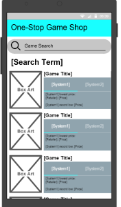
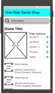
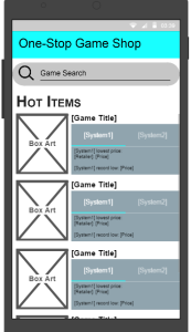
With my tool chosen, I began work on the design of my app.  I chose to create something that I had been wanting for a while now: an app that aggregates video game prices to help its user find the best deal available to them.  I wanted to be able to search for a game, then see what its current lowest price is on all of its available platforms, as well as what each platform’s all-time lowest price was, to help me decide if I should wait a bit to get an even better deal.

The app itself was rather simple to make, with only three different screen layouts.  All pages have a title bar and a search bar at the top, allowing for easy access to a new query.  The home page lists some of the current ‘Hot Items’ which would be decided on by an algorithm that takes into account both search frequency and unusually good deals.  Each game in this list would have a tab next to it for each platform the game is released on, allowing the user to get an idea of what that game’s best deals are without having to change screens.

mobile home

The search screen brings up a list in the same style as the ‘Hot Items’ list, but with results based on your search terms.  Clicking a game’s name or box art in either of these lists takes you to that individual game’s page.  This page lists the current lowest prices available for the game at different retailers, as well as a checkbox filter that lets the user narrow down their search to any combination of platforms the game is available for.  It also lets the user search for physical disks, digital codes, or both, though attempting to uncheck both the physical and digital boxes would result in an empty list.  Tapping on a store in the list would then take the user directly to that game’s page on the store’s website, if available, to make the purchase.

mobile search mobile game

Designing this app felt good to me, as it is something I have wanted in my life for a long time, but unfortunately I had more problems with my tools this week.  While proto.io is a surprisingly powerful web application, its very nature as a web application meant that any time I lost my wireless connection (a regular occurrence at my house) I was stick waiting for the app to reconnect.  However even with a good connection there was also a minor amount of lag between my inputting a command and the application acting on it, which made the app as a whole feel unresponsive.  Despite last assignment’s issues with publishing, I found myself desperately wanting a desktop version of the app to use offline and lag free.  The features are there with proto.io, but its demand for connectivity is what ended up making me wish I could create this with code yet again.

The demo for my prototype can be found here as of this writing, however my trial membership with the service has expired and I am not sure if the project will stay hosted forever.  Hopefully there won’t be too many issues with that.

Thanks for reading!

Website Wireframe

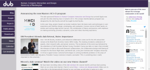
Having finished our Wizard of Oz prototypes, the class began work on creating wireframe redesigns of the UW’s dub website.  Dub is a cross-campus group that focuses on Human Computer Interaction and Design, however it has been years since their site has been updated, let alone designed, making it a great sandbox to practice wireframing in.

dub site
dub.washington.edu

I chose to create my wireframe in Axure, a program designed to create prototype systems of varying fidelities.  Being a wireframe, most of the content on my design would be placeholder, from images to text.  The only actual written text on the page was either used to describe what the placeholder was holding the place of, or as headers for the various parts of the page.

Looking at the current layout of the dub site, one thing I was struck by was that the only thing updated in the last year or more was the automated twitter feed in the right margin.  I decided that since this would provide for a steady stream of effortless content, I chose to keep it in my redesign of the site.  The rest of the site’s design was based on a mixture of the things already found on dub and the assignment’s requirements.

We were given announcements, directory, calendar, seminar, research, and membership as required content, and going through that list I noticed that the only thing the current dub site has that this didn’t cover was the blog, which I didn’t consider an entirely bad thing.  A lack of updates on the blog was the first sign that the dub site was in trouble, and even if other parts of the site are being updated the empty blog gives users the impression that the site has been abandoned.  Losing the blog may have removed a front-and-center place to put a specific kind of content, but that content could either be posted on personal blogs and linked to in the Twitter feed, or put in the blogger’s page in the directory.

With the headings decided on, it came time to design the content of individual pages.  Lining the page up with a 12 column 960px grid, the first thing I did on the main page was put an ‘About’ blurb at the top of the content area.  This was a section that was noticeably lacking on the current dub page, which was made apparent to me when I found out from one of their contributors that I, at the time, had a fundamental misunderstanding of what dub was.  Underneath of the About section I wanted to put easy to notice windows to what would likely be the two most often referenced parts of the site: the announcements and calendar.

Designing the rest of the pages was a fairly straightforward process, as I only had to create placeholder content to fulfil the needs of that page.  This became slightly more complicated with the seminar and research pages since there were multiple types of information that needed to be conveyed through them, but I found that I could easily break those pages into four different subjects to explore within the topic.

The final design for my wireframe can be found here.  After creating it, I noticed several strange issues with the way the page looked.  First was the fact that it seems like the font in the published version of the wireframe is different from what I was viewing in Axure, as some text is now much larger, expanding out of their containers.  The other issue is that while in Axure the Twitter feed bar had scroll buttons on it to indicate that there was more to be found than just the tweet and a half, those disappeared with the published version.

In the end, I found my experience with wireframing to be educational, but my time spent with Axure was frustrating.  As a web developer with several years of experience, I couldn’t help but feel like I was taking the long way around by using the supposedly ‘rapid’ prototyping tool, especially considering the inconsistancies between my local and published versions.  I went into the assignment knowing it would be slower since I would have to learn new software on top of designing the site, and I obviously still have a lot to learn about the software, but I still feel conflicted about whether it is worth giving up the power of commanding the computer through code, even if just for a prototype.

Thank you for reading!

Wizard of Oz prototype

After the video prototype, the class was split into groups to create a behavioral prototype, alternately called a Wizard of Oz prototype.  This type of prototype uses whatever methods the prototyping team has available to simulate the product that they want to test, often attempting to keep the test’s participants oblivious to the fact that there is someone ‘behind the curtain’ who is actually controlling the prototype.  It is often used to get feedback on the initial design and functionality of a product that would be too expensive to create a more high-fidelity prototype.

For our project we were told to create a behavioral prototype for either a speech-to-text system, a wearable posture detection system, or a gesture recognition system, which is what we chose to create, in the form of a gesture controlled music app.  To achieve the sensor effect of the music player, we chose to take the advantage of the premium version of Spotify music player, which allows us to remotely control the player on mobile devices from laptop.  By using it, we successfully played around with the basic gesture controls including play/pause/next song/previous song.  The technology is also affordable, and easy to set up: all we used were a laptop and a tablet with Spotify premium installed.

We next assigned roles to each of the group members for the test.  I was enlisted to be the test’s moderator, with Juan Cai taking filming duties.  We introduced Rashmi Srinivas and ‘Hailey’ Xiaochen Yu to our participants as notetakers, while in reality Hailey was watching the participant’s gestures and controlling the tablet’s Spotify app from her computer.  We set up our group and equipment in an alcove at UW’s Allen Library and began our recruiting efforts.

Watch our video here:

Rashmi and I began by walking the library to see if we could find anybody, but quickly realized that anyone already there was likely going to be busy and not want to be disturbed, so we instead set up camp by the library’s entrance to recruit people coming or going.  Finding someone fairly quickly, we introduced the team as a joint HCDE and CSE group (not actually a lie) who had created a gesture recognition system that runs in Spotify’s background, and began our first round of testing.

After setting up the user, we faced a surprise challenge.  It turned out that Rashmi and I took long enough finding the participant that the connection between the laptop and tablet had timed out, meaning that when Hailey tried to give the tablet the ‘Play’ command, the sound instead came from her laptop and a connection request dialog box appeared on the tablet.  There was a moment of confusion for everyone present, with the user asking if the volume was turned down on the tablet.  I realized what had happened before long and took the tablet from the user, giving the Pause gesture to the device and Hailey before confirming the connection to the laptop.  Explaining this as a bug in our system, I put the tablet back in front of the user to get to the test proper.

From there, our first test went very well.  I had the user run some very simple play/pause tests as well as a skip forward and skip back command.  At the end of the test, he seemed impressed with our ‘app,’ leading us to believe that he was fooled by the test despite the technical issues it started with.  For good measure we chose to recruit a second participant, who we found and ran the tests with successfully, completely fooling her, with only one interesting problem.

Looking back at the tests, we realized that one thing we should have done was train the user on the gestures before sitting them down in front of the device.  For the most part, the gesture descriptions were enough for the participants to successfully use the device, however our second participant’s Play/Pause wave looked incredibly similar to the swipe used to skip forward a song, leading to Hailey having to make a hasty decision about which command to give the tablet.  Had we trained the user, we wouldn’t have had to make that quick decision which, in our test, ended up with us having to react to that motion as the Play/Pause command for the sake of consistency.

Thank you for reading!

Video Prototype

Our next project was to create a video prototype of one of a selection of transportation apps.  I chose to work with the One Bus Away app, as it was one I had a large amount of experience with and was familiar with a variety of use cases for it.

For the unfamiliar, One Bus Away is an app that lets users see how long it will be before a bus shows up to a stop, taking delays and early arrivals into account.  It also allows users to look up bus routes and mark favorite stops and routes, but the scheduling aspect of the app is its main draw.

After some brief brainstorming I decided that the use case I wanted to show was somebody trying to plan a night out, who would use the app to determine what he had time to do before leaving his place.  I chose this because it was a scenario where the app was making an active difference in the way the user behaved, versus the many other use cases where the app plays a more passive role in the user’s life.

From here I decided to take a more atypical route in the planning stages of the video.  Instead of sitting down and drawing a storyboard, I instead turned on the camera and began ad-libbing in the general direction I wanted to go.  As I came across lines or variations that I liked I would write it down in a script, eventually having a full script that ran about a minute long.  I shot and edited the video over the course of a night, then recorded a voice over the next morning to replace the audio from my cell phone.

Here is my final video:

In the end, I’m fairly happy with the way it turned out, especially for having next to no video editing experience. I was a bit disappointed with the lighting I had available since it could be difficult to see the iPod’s screen.  Also, a side-effect of filming late at night was that it was difficult to find stops that had busses coming through in a time frame that made my scenario believable. Despite these setbacks, I’m very happy with the way the video turned out.

Thank you for reading!

3D Printing the Buster Sword

From creating 2D shapes to be cut, the class took what it learned in Rhino 3D and applied it to 3D modelling with the purpose of 3D printing our designs.  The assignment was fairly open ended, with the only requirements being that our model needed to have an extrusion, a revolution, and at least one Boolean union or Boolean cut operation in it.  After some deliberation, I decided to model the Buster Sword from Final Fantasy VII for my project.

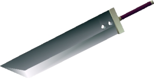
Buster_sword_2_FF7
The Buster Sword as seen in Final Fantasy VII on the original Playstation

There were several reasons why I chose this besides just being a cool sword.  Because the sword’s design is very geometric, I knew I could have a rough model of it done very quickly and use that to figure out any quirks involved with Rhino models.  Once I got to the polishing phase of the design, there was also a wide variety of extras I could work into it depending on how much time I had left.  The Buster Sword has seen several redesigns in its appearances, going from what is essentially a steel slab on a stick in the first game to a more ornate design with engravings and embellishments in more recent appearances.  By starting with that most basic version of the sword, I was able to gauge how much of those extras I would be able to work in with my time left.

The modelling process seemed fairly straightforward until I tried to save my model as an STL file, which requires that the model be closed.  Apparently, unbeknownst to me, there were many edges that could not join together for one reason or another, as well as a section on the curve of the blade that didn’t fill in entirely.  I chose to tackle the problem with the curve first, since it would be the problem that would be most obvious when fixed.  It also proved to be relatively simple to fix.  After toying with different Rhino tools to make surfaces out of edges and curves, I found the Patch tool to do exactly what I was looking for, while the rest didn’t cooperate with the curve I wanted very well.

Fixing the rest of the model’s problems proved to be much more involved and time consuming.  The culprit ended up being a concept I was not aware of, that being Naked Edges.  It was my assumption that if I created two surfaces using some of the same edges, those surfaces would be created joined at those edges.  Unfortunately this assumption was incorrect, and led to many edges that were unconnected, or Naked, and weren’t always easy to connect.  At this point in the process it took hours of digging through my model deleting surfaces that touched edges and recreating them to perfectly fit the space I needed them to fill.  This was particularly difficult in several cases where, for reasons unknown to me, edges had split themselves into two segments: one that comprised most of the edge and another which covered the last millimeter or so.

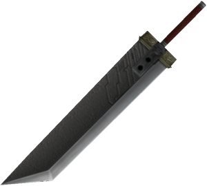
Buster_Sword_-_Crisis_Core
The Buster Sword as seen in Crisis Core: Final Fantasy VII on the PSP

With this taken care of, I decided to spend some time adding a few of the embellishments found in the sword’s later appearances.  The first of these that I did was to raise the area around the two slots on the blade to match the hilt’s width, as I found this to be a distinguishing feature of the newer versions.  Next I wanted to do something with the hilt, but was not up to the task of recreating the ornate design found on most modern versions of the sword.  I noticed that the design found in the fighting game Dissidia: Final Fantasy, which was meant to evoke a more classic feel, had five rivets on either side of the hilt.  I was able to incorporate those by creating a sphere that poked less than halfway out of the hilt, then doing a linear repeat down the length and mirroring it to the other side.

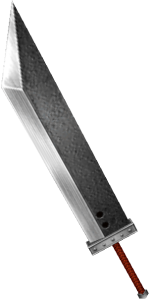
Dissidia: Final Fantasy's version of the Buster Sword
Dissidia: Final Fantasy’s Buster Sword

The final extra I included was one that I had hoped to be able to from the beginning, but was most worried about: a helical threading winding up the handle.  To start with, I found the helix curve function in Rhino and made the curve extend the length of the handle.  I then experimented with the number of curves needed to get the appropriate spacing, which I found to be three curves going in either direction.  The hard part then was finding the way to turn those curves into a 3D object to add to the model.  In my head this would be accomplished by sweeping a circle along the helixes, but this ended up creating flat edges at the 90 and 270-degree marks on the helix as the circle was fixed in its orientation while it followed the helix instead of rotating along the curve.  After a lot of hunting and almost giving up on the feature, I discovered the Pipe function in a Rhino tutorial, which creates a solid object using a curve and a radius from the curve.  This perfectly solved my problem, and ended up looking very nice with 0.5mm-radius pipes coiling up the handle.

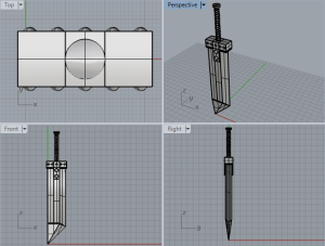
View in Rhino3D of the Buster Sword model

Once everything was joined in a single solid body, I opened the STL file in Makerbot Desktop to prepare the model to be printed.  I had hoped to print the sword standing on its handle to minimize the surface area requiring supports to be printed, however, my model was too tall to print in that orientation and I didn’t want to scale it down for fear of losing the quality of some of the smaller components.  Laying it on its side made the model fit on the printer’s tray, but the rivets on the hilt also meant that almost the entire side I printed it on would require supports in order to print.  In the end, I chose to bite the bullet (or more appropriately, PLA) and print it this way.

The printing process went extremely smoothly.  I chose to print at a standard .2mm resolution with a 20% infill, which allowed a surprising amount of detail.  I had worried while modelling that the threading on the handle would be too small to print well, but was pleasantly surprised by the end result.  Removing the supports was time consuming but not difficult with the right tools, though there is a single support inside of the hilt’s guard that I haven’t been able to remove yet.  Once the rest were removed though, I took some sandpaper to the parts that were held up to smooth them out.  The one part this proved problematic with, though, was the handle.  Because the threading on the handle is so fine and textured, trying to sand the ridges from the supports off of the threads was impossible to do without sanding off the threads themselves.  Knowing now how well the threads came out I would be more comfortable putting the sword on its handle and scaling it down just a bit to make it fit, greatly reducing the surfaces requiring supports and only supporting parts that can be sanded flat without worrying about losing any features.

In the near future I may end up painting this with some friends, and will update this post with pictures of the finished product once I do.  Thank you for reading!

Laser Cutting a Phone Holder

From the model prototype, the class moved on to making a 2D digital prototype to be laser cut out of mat board.  We created this in Rhino 5 using curves in the top viewport, and then sent the file to be laser cut into a phone holder to use for filming later in the course.

I struggled with ideas at first, so I decided to take some scrap cardboard I had around the house and make a prototype for my prototype. Early on I decided that I wanted a sort of U shape for the holder, but had some trouble deciding how I would have that shape hold the phone upright. I didn’t want to rely on the walls of the U to hold it in place both because I knew if I did that then they would eventually bow outward and become useless, and also because that would require very precise measurements, which were difficult to do with the tools I had on a phone case with curved edges. Eventually I decided to use two sticks inspired by popsicle sticks to hold the top of the phone in place while letting the bottom rest freely on the floor of the stand, allowing it to be angled up or down within the case.

From there I moved on to modeling the holder in Rhino. Since I have experience working in SolidWorks, working with curves on a single plane was quite straightforward. I quickly made a base for the U with slits 15cm apart to connect to the walls, which I then modeled along with the sticks. It was at this point that I realized that with the plan as it was, there was nothing to keep the walls from wearing out and falling over to the point that they wouldn’t support the sticks anymore, so I etched some slits where the sticks would be against the walls to secure both them and the walls in place. With that done, I also realized that I didn’t want the walls to be acting as stilts for the entire camera holder, so I put a score across each side of what was left of the section of the walls I cut the slit from. This created a tread that would allow the piece to bend at that point and fold under the floor.

With the structure fully designed, I decided to make a few aesthetic adjustments to it as well. Half because I wanted to save material and half because diagonal lines look cool, I decided to cut a wedge out of the walls of the U shape. I then rounded the ends of the sticks to make them better resemble their inspiration. As I did this, I realized that it would both look good and save me from unnecessary stab wounds if I beveled all of the external corners on the design. With these changes made, I sent my design to the laser cutter for a first pass.

On doing the first cut of my design I was pleased to know that most of it worked exactly as planned, with two caveats. The first was with the hinges I created. Not knowing how thick the laser would cut into the board, I only scored two lines into the hinge. I learned while looking at my first prototype that this single tread did not let the board bend as fluidly as I wanted it to. Fortunately, I also learned that the laser’s scoring is very thin, which gave me more than enough room to fit another line into the design, solving the problem. The second problem was with the slots I cut to slide the popsicle sticks through. I had made them 1.2mm wide, the same as the slots used to hold the pieces together, however I learned that while this width is suitable for when a tight lock is desired between the two pieces, it made it very difficult to insert the sticks through the slot, and even worse getting it through the second one. I took an X-acto knife to the slot, widening it very slightly to make sure that would adequately solve the problem, which it did. After running my board through a second cut I was successfully able to build and take apart the phone holder.

Thank you for reading! I will have images added to this post as soon as I can sort them all out from my camera.

Model Prototype of a Digital Shower Controller

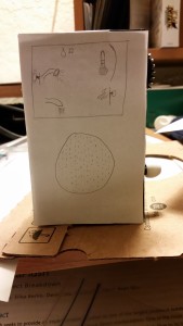
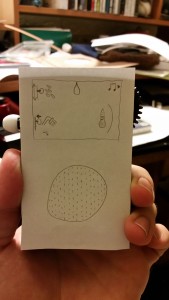
Not long ago the class was tasked with creating a model prototype for one of three design ideas, one of which being a digital shower controller.  The design prompt was to mimic OXO’s universal design philosophy, and one of the design notes reminded us that, as users would be in the shower, they would not have any corrective lenses they may wear and their precision with touch interfaces may be reduced due to being wet.  With these in mind, I decided to make most of the controls for the system physical, and the only touch-based commands to be very general, not requiring any form of precision.

My first pass at the design was a roughly 2″x4″ box made of Lego with a 1.5″ cog on the top of the right side and a slider with a button covering the rest of the side.  The Lego was initially chosen due to the convenience of both materials and ability to modify, but it also had the benefit of having ridges on the back, improving the grip for when used in a wet, slippery environment.  To emulate the UI, I created a paper front for the model with a mockup of the UI and a speaker drawn on it.

rev1 1rev1 2

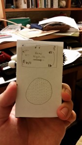
My usability test was very informative, and led to several changes in my design that I feel improved it significantly.  The key change I made was actually based on an observation I made outside of the structured test, that being that the user had to use two hands in order to operate the device fully.  By moving the slider to the opposite side of the device, the user is able to operate one of the controls with their thumb and the other with their pointer finger, allowing for one-handed use.

This change also allowed for some UI changes that made some operations more apparent.  Due to screen space, I initially had the cog and slider controls displayed on the right side (the same side as the controls), but had to place the button display on the other side.  By moving the slider to the other side the slider and button controls could be next to each other, implying their connectivity, which was something my participant had trouble figuring out on their own.  I also changed the icon for the button to make it clearer that it is something to be pressed.

My user also had trouble figuring out how to move from the shower control screen to the music player.  I had used an icon layout inspired by phone screen navigation icons intending to imply that the user had to swipe to get from one screen to the next, but my user instead tried to tap on the icons to switch screens.  In order to make it clearer that the music player lies “offscreen” to the right, I moved the icon for the player to the top-right corner of the screen with an arrow pointing towards the edge of the screen.

rev2 1rev2 2

It is worth noting that while my user was having trouble finding how to switch screens during the usability test, I caught myself making a slight misstep.  After he had indicated that his first instinct would be to touch the icon instead of swiping the screen, I asked him what he looks for to indicate that a screen needs to be swiped.  The question itself is good, I believe, but before asking it I should have asked what he would have done if tapping had not worked.  As it was, his response was “Oh, swiping would have been what I would have tried next,” but not having asked the question before giving him the solution throws the validity of that statement out the window.  Even so, I believe the change I made to address the issue was worth making, as it leaves little to no doubt what interaction the device is looking for.

You can find an abridged, one-minute version of my usability test here.  Thank you for reading!
Smart Phone/Watch app paper prototype

Our first assignment in the class was to design and create a paper prototype for an app that makes use of both a smart phone and a smart watch, such as the Pebble or the Apple Watch.

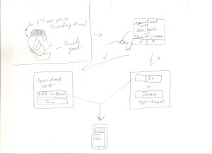
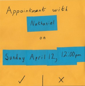
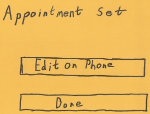
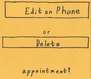
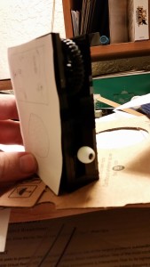
As someone who has been trying to make better use of the calendar functions on my phone, I thought it would be fitting to design an app that would help facilitate that.  My design has an app running on the watch and phone listen to calls being made for specific dates or times mentioned by either person, and then puts together a calendar event for those times.  It gives the user the option to approve or deny the offered appointment, and if the user approves, asks if they would like to edit the appointment on their phone, or finish with the process.  A similar screen appears if the user declines the appointment, with buttons to edit the offered appointment on your phone or to exit without creating a calendar event.

Sketch0001-page-0

Based on this design, I created a paper prototype of the app as it would appear on the user’s watch.  I wrote post-its for any variable fields, allowing for some differences between test sessions, though for the sake of time and resources I limited the options here to a single week in April (Sunday the 12th to Saturday the 18th).

Paper Prototype0001-page-0
scan0025

scan0024


My testing of the system went very well, with users intuitively knowing how to interact with what they were seeing.  One tester commented that he found it strange that both confirming or declining the offered appointment gave them the ability to edit the appointment’s parameters, though he did also say that he could imagine himself in circumstances where he would accept the appointment and want to add details, as well as situations where the offered option was far enough from what he wanted that he did not want to go with it, but would want to edit it.

One thought that crossed my mind was that it may be helpful to have the first screen have accept and reject buttons, but also an edit button, which removes the need for the other two screens altogether.  My one worry with this option would be that we would run out of real estate on the watch screen, since they are so small.  This is something I would have to explore in further testing were I to continue with the project.

Week 1

Over the first week of the quarter, our class had several introductory exercises and activities.  On Tuesday we were shown around the Makerspace we will be working in for the quarter and given an idea of what to expect in the class.

On Thursday we dove into the Paper Prototyping process.  After breaking up into groups, we designed and prototyped a tablet-based coffee ordering system according to specifications given to us by our professor, Andy Davidson.  Working with Juan Cai and Jessica Wong, we drafted several ideas on a whiteboard before deciding on a final one, which we then built our paper prototype of.

The system was required to have three different types of drinks (Espresso, Macchiatto, and Cappuccino) in three different sizes (Normale, Grande, and Gigante), and to not only disallow add-ins like caramel or white chocolate, but to admonish users for trying to add them.  Our design’s main screen had a wide button for the three drinks spaced vertically on the page.  When the user chooses the drink they want, the buttons transform into the size options.  After a size is chosen, they are returned to the main screen.  There is a persistent ‘order’ tab on the right side of the page which keeps a running total of the user’s order and lets them check out.

Regarding the ‘add-ins’ part, we wanted to find a way of including the admonishment without offering fake drink options baiting people into coming across the message.  Instead, since the three drinks offered fill the vertical screen space, we thought that people looking for more than those three drinks would try to scroll down the page to find them and put a message below the fold that doubled as a mission statement for the fictional cafe.

We conducted a usability test afterward which inspired some subtle tweaks to the system (having the order tab show the current total on it being one), but I think the end result was a very good, usable design.