From creating 2D shapes to be cut, the class took what it learned in Rhino 3D and applied it to 3D modelling with the purpose of 3D printing our designs. The assignment was fairly open ended, with the only requirements being that our model needed to have an extrusion, a revolution, and at least one Boolean union or Boolean cut operation in it. After some deliberation, I decided to model the Buster Sword from Final Fantasy VII for my project.
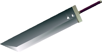
There were several reasons why I chose this besides just being a cool sword. Because the sword’s design is very geometric, I knew I could have a rough model of it done very quickly and use that to figure out any quirks involved with Rhino models. Once I got to the polishing phase of the design, there was also a wide variety of extras I could work into it depending on how much time I had left. The Buster Sword has seen several redesigns in its appearances, going from what is essentially a steel slab on a stick in the first game to a more ornate design with engravings and embellishments in more recent appearances. By starting with that most basic version of the sword, I was able to gauge how much of those extras I would be able to work in with my time left.
The modelling process seemed fairly straightforward until I tried to save my model as an STL file, which requires that the model be closed. Apparently, unbeknownst to me, there were many edges that could not join together for one reason or another, as well as a section on the curve of the blade that didn’t fill in entirely. I chose to tackle the problem with the curve first, since it would be the problem that would be most obvious when fixed. It also proved to be relatively simple to fix. After toying with different Rhino tools to make surfaces out of edges and curves, I found the Patch tool to do exactly what I was looking for, while the rest didn’t cooperate with the curve I wanted very well.
Fixing the rest of the model’s problems proved to be much more involved and time consuming. The culprit ended up being a concept I was not aware of, that being Naked Edges. It was my assumption that if I created two surfaces using some of the same edges, those surfaces would be created joined at those edges. Unfortunately this assumption was incorrect, and led to many edges that were unconnected, or Naked, and weren’t always easy to connect. At this point in the process it took hours of digging through my model deleting surfaces that touched edges and recreating them to perfectly fit the space I needed them to fill. This was particularly difficult in several cases where, for reasons unknown to me, edges had split themselves into two segments: one that comprised most of the edge and another which covered the last millimeter or so.
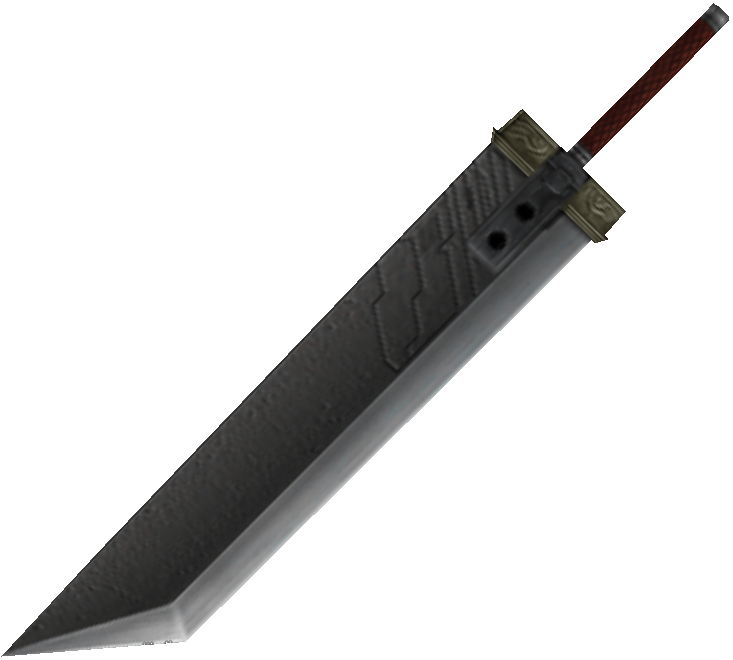
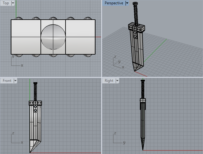
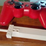
With this taken care of, I decided to spend some time adding a few of the embellishments found in the sword’s later appearances. The first of these that I did was to raise the area around the two slots on the blade to match the hilt’s width, as I found this to be a distinguishing feature of the newer versions. Next I wanted to do something with the hilt, but was not up to the task of recreating the ornate design found on most modern versions of the sword. I noticed that the design found in the fighting game Dissidia: Final Fantasy, which was meant to evoke a more classic feel, had five rivets on either side of the hilt. I was able to incorporate those by creating a sphere that poked less than halfway out of the hilt, then doing a linear repeat down the length and mirroring it to the other side.

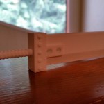
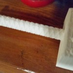
The final extra I included was one that I had hoped to be able to from the beginning, but was most worried about: a helical threading winding up the handle. To start with, I found the helix curve function in Rhino and made the curve extend the length of the handle. I then experimented with the number of curves needed to get the appropriate spacing, which I found to be three curves going in either direction. The hard part then was finding the way to turn those curves into a 3D object to add to the model. In my head this would be accomplished by sweeping a circle along the helixes, but this ended up creating flat edges at the 90 and 270-degree marks on the helix as the circle was fixed in its orientation while it followed the helix instead of rotating along the curve. After a lot of hunting and almost giving up on the feature, I discovered the Pipe function in a Rhino tutorial, which creates a solid object using a curve and a radius from the curve. This perfectly solved my problem, and ended up looking very nice with 0.5mm-radius pipes coiling up the handle.
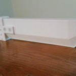
Once everything was joined in a single solid body, I opened the STL file in Makerbot Desktop to prepare the model to be printed. I had hoped to print the sword standing on its handle to minimize the surface area requiring supports to be printed, however, my model was too tall to print in that orientation and I didn’t want to scale it down for fear of losing the quality of some of the smaller components. Laying it on its side made the model fit on the printer’s tray, but the rivets on the hilt also meant that almost the entire side I printed it on would require supports in order to print. In the end, I chose to bite the bullet (or more appropriately, PLA) and print it this way.
The printing process went extremely smoothly. I chose to print at a standard .2mm resolution with a 20% infill, which allowed a surprising amount of detail. I had worried while modelling that the threading on the handle would be too small to print well, but was pleasantly surprised by the end result. Removing the supports was time consuming but not difficult with the right tools, though there is a single support inside of the hilt’s guard that I haven’t been able to remove yet. Once the rest were removed though, I took some sandpaper to the parts that were held up to smooth them out. The one part this proved problematic with, though, was the handle. Because the threading on the handle is so fine and textured, trying to sand the ridges from the supports off of the threads was impossible to do without sanding off the threads themselves. Knowing now how well the threads came out I would be more comfortable putting the sword on its handle and scaling it down just a bit to make it fit, greatly reducing the surfaces requiring supports and only supporting parts that can be sanded flat without worrying about losing any features.
In the near future I may end up painting this with some friends, and will update this post with pictures of the finished product once I do. Thank you for reading!